and the distribution of digital products.
Turning Flat Images into 3D Worlds: The Math and Mechanics Behind Stereo Vision
\
\
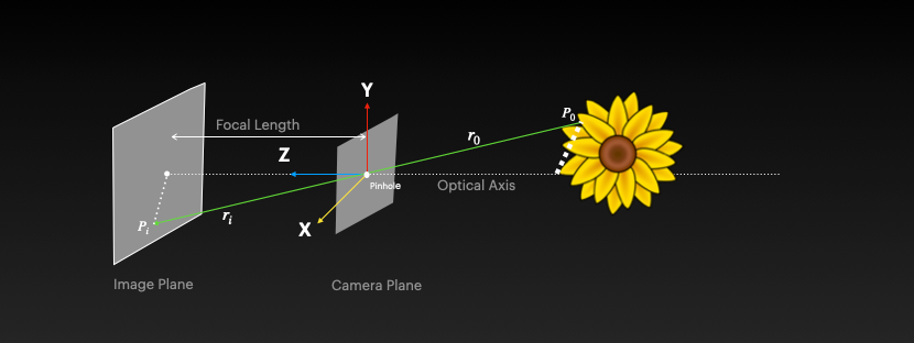
Basic Definitions- The object (flower) is said to be in the world and its position is given by world coordinates in 3D (x,y,z)
- Now imagine the light rays from the object pass through a hole and get projected on a wall. The wall is the IMAGE plane and the hole it passes through is called the PINHOLE. The camera is placed at the pinhole. The camera is said to be in the CAMERA plane
- The distance between the camera placed at the pinhole and the wall (image plane) is called FOCAL LENGTH
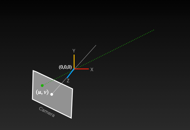
When we capture an image, the 3D world coordinates (x,y,z) undergo two critical transformations:
- First, they are TRANSFORMED into the camera's coordinate system (still 3D)
- Then, they are PROJECTED onto a 2D image plane
\ This process follows the path: WORLD → CAMERA → IMAGE. This sequence is known as the Forward Imaging Model. The specific projection from the camera coordinate system to the 2D image plane is called Perspective Projection. Through this process, a 3D object is converted into a 2D image.
\ In certain applications, we need to reverse this process - obtaining 3D coordinates from a 2D point in an image. ==This challenge is referred to as finding depth in an image==. Essentially, we ask: "Given any point in the image (U,V), can we determine its corresponding point in the 3D world?" When analyzing this reverse process, we discover that while information is lost during projection, we haven't completely lost the "X" and "Y" information. This gives us hope for recovery with additional contextual information. Since we know the 2D coordinates, we can determine that the 3D point must exist somewhere along a specific projection line (visualized as dotted green lines in diagram below). This same line that was used in the original forward projection can assist us in the reverse mapping process as well.
\
\
Nature has provided us with an elegant solution for perceiving depth through binocular vision. Our two eyes, positioned horizontally at a distance from each other (interpupillary distance), each capture a slightly different perspective of the world. This principle is the foundation of stereoscopic vision and depth perception.
The Stereo Vision Process- Biological Inspiration: Humans perceive depth naturally because our brain combines the slightly different images from our left and right eyes. This difference in perspective allows our visual system to triangulate and determine the distance to objects.
- Computational Implementation: By mimicking this biological approach, we can recover 3D information using two cameras:
- We position two cameras horizontally along the same axis, separated by a known distance (the baseline "b")
- We identify the same point in both camera views (correspondence problem)
- We project rays from each camera through these corresponding points
- The intersection of these projection rays (the "dotted green lines" in the visual) gives us the 3D coordinates including depth (Z)
- Triangulation Process: When we identify a point (ul, vl) in the left camera and its corresponding point (ur, vr) in the right camera, we can reconstruct its 3D position through geometric triangulation. The difference between these corresponding points (called disparity) is inversely proportional to the depth - larger disparities indicate closer objects.
- Mathematical Foundation: This approach works because each camera provides a constraint on where the 3D point can be located. While a single camera can only determine that a point lies somewhere along a ray, two cameras create two rays whose intersection uniquely identifies the point's position in 3D space.
\ This stereo vision approach is the fundamental principle behind many depth-sensing technologies, including 3D reconstruction, autonomous navigation systems, and mixed reality applications.
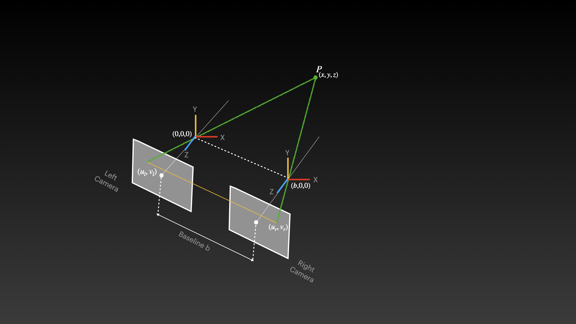
The points (ur, vr) and (ul, vl) represent the same 3D point as it appears in the right and left camera images respectively. These corresponding points are crucial for stereo vision as they establish how the same physical point projects differently onto each camera's image plane. The horizontal displacement between these corresponding points is called disparity and is inversely proportional to depth - objects closer to the cameras have larger disparities than distant objects.
\ The coordinate system in stereo vision is carefully defined to facilitate calculations:
- The left camera is positioned at the origin (0,0,0) and serves as the reference frame for the entire system
- The right camera is positioned at (b,0,0), meaning it's displaced only along the X-axis
- Both cameras are typically aligned with parallel optical axes to simplify the epipolar geometry
- The Z-axis points along the cameras' viewing direction, with X horizontal and Y vertical
To compute the 3D coordinates of point P(x,y,z) using stereo vision:
- Camera Calibration: First, both cameras must be calibrated to determine their intrinsic parameters (focal length, principal point) and extrinsic parameters (relative position and orientation)
- Feature Detection: Identify distinctive features in both images that can be reliably matched
- Correspondence Matching: Find the same point in both camera views using techniques like block matching, feature matching, or semi-global matching
- Disparity Calculation: Compute the horizontal displacement between corresponding points
- Triangulation: Use the disparity, baseline, and camera parameters to calculate the 3D position through projection ray intersection
The actual 3D coordinates can be calculated using these formulas (for a simplified rectified case):
- ==x = (ul × z) / f==
- ==y = (vl × z) / f==
- ==z = (b × f) / (ul - ur)==
\ Where f is the focal length of the cameras.
Applications and ImpactStereo vision serves as the foundation for numerous depth-sensing technologies and applications:
- Robotics and Autonomous Navigation: Enabling robots and vehicles to perceive their 3D environment
- 3D Reconstruction: Creating detailed 3D models from multiple 2D viewpoints
- Mixed Reality: Anchoring virtual content in the physical world through spatial mapping
- Industrial Automation: Facilitating precise measurement and inspection tasks
- Medical Imaging: Assisting in minimally invasive surgeries and diagnostics
- Satellite Imaging: Creating elevation models from different orbital viewpoints
\ This fundamental approach to recovering 3D information from 2D projections continues to evolve with advancements in computational efficiency, matching algorithms, and integration with other sensing modalities.
References