and the distribution of digital products.
Meet PAUL: A Soft Robot That Moves with Air Pressure
:::info Authors:
(1) Jorge Francisco Garcia-Samartın, Centro de Automatica y Robotica (UPM-CSIC), Universidad Politecnica de Madrid — Consejo Superior de Investigaciones Cientıficas, Jose Gutierrez Abascal 2, 28006 Madrid, Spain ([email protected]);
(2) Adrian Rieker, Centro de Automatica y Robotica (UPM-CSIC), Universidad Politecnica de Madrid — Consejo Superior de Investigaciones Cientıficas, Jose Gutierrez Abascal 2, 28006 Madrid, Spain;
(3) Antonio Barrientos, Centro de Automatica y Robotica (UPM-CSIC), Universidad Politecnica de Madrid — Consejo Superior de Investigaciones Cientıficas, Jose Gutierrez Abascal 2, 28006 Madrid, Spain.
:::
Table of Links2 Related Works
3 PAUL: Design and Manufacturing
4 Data Acquisition and Open-Loop Control
4.3 Dataset Generation: Table-Based Models
5 Results
5.3 Performance of the Table-Based Models
5.5 Weight Carrying Experiments
A. Conducted Experiments and References
AbstractSoft Robots distinguish themselves from traditional robots by embracing flexible kinematics. Because of their recent emergence, there exist numerous uncharted territories, including novel actuators, manufacturing processes, and advanced control methods. This research is centred on the design, fabrication, and control of a pneumatic soft robot. The principal objective is to develop a modular soft robot featuring with multiple segments, each one of three degrees of freedom. This yields to tubular structure with five independent degrees of freedom, enabling motion across three spatial dimensions. Physical construction leverages tin-cured silicone and a wax casting method, refined through iterative processes. 3D-printed PLA moulds, filled with silicone, yield the desired model, while bladder-like structures, are formed within using solidified paraffin wax positive moulds. For control, an empirically fine-tuned open-loop system is adopted. The project culminates in rigorous testing bending ability and weight carrying capacity and possible applications are discussed.
\ Keywords: soft actuator; pneumatics; soft robots materials and design; open-loop control; computer vision capture
1 IntroductionThe rapid growth of soft robotics in the past decade is driven by their versatile applications in various fields, such as assisting surgeons, taking care of elderly people [1, 2], aiding rehabilitation [3], and enhancing manipulation capabilities [4]. Soft robots significantly differ from their traditional rigid counterparts, demanding innovative solutions across a wide spectrum, encompassing sensors, actuators, and control techniques.
\ While conventional actuation methods can be applied in certain scenarios, such as cable robots where external motors tension the cables [5,6], novel actuators are frequently required. This has led to the development of various actuator types, including pneumatic actuators [7], electroactive polymers (EAP) [8], magnetic actuators [9], twisted and coiled actuators (TCA) [10], and shape memory alloys (SMA) [11, 12].
\ Among these options, pneumatic actuators stand out due to their cost-effectiveness, simplified manufacturing, straightforward actuation, and impressive load-bearing capacity [13], specially when no high speeds are required. Certainly, these actuators do not necessitate specific manufacturing conditions beyond the curing of silicone, typically conducted at or near room temperature. Moreover, their operation does not demand high-voltage conditions or the generation of external magnetic fields. Furthermore, they excel in achieving continuous deformations in the robots, surpassing those actuated by wires.
\ These advantages have led to their use in grippers [14], inspection tasks [15], locomotion robots [16, 17] wearable devices for rehabilitation [18] or imitating human body parts [19].
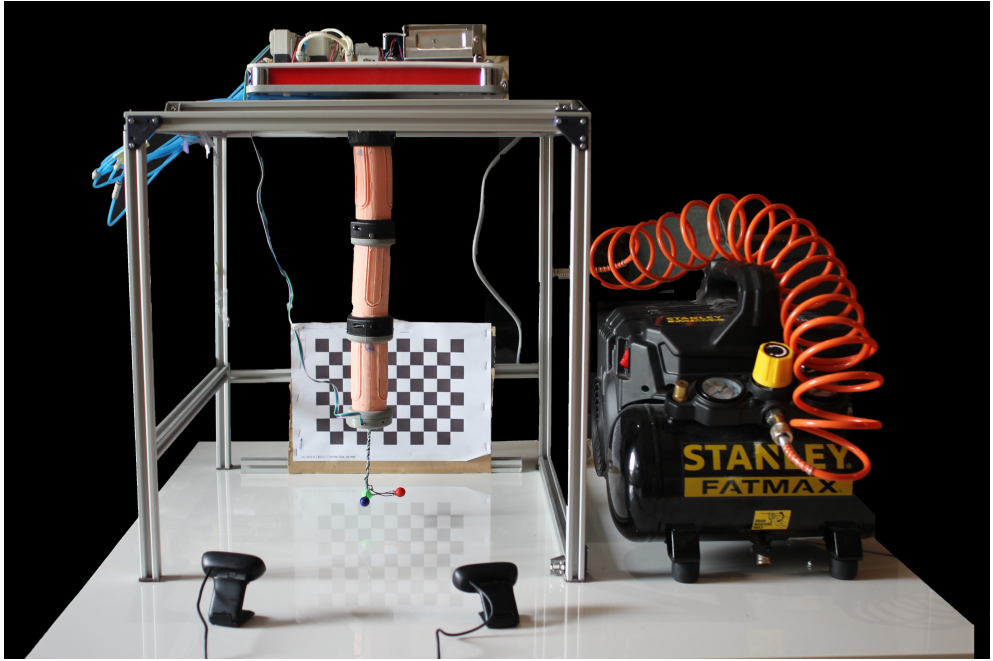
\ The main contribution of this work has been the design, manufacturing and open-loop control of a 5-degrees of freedom (DOF) soft pneumatic arm called PAUL (Pneumatic Articulated Ultrasoft Limb) and depicted in Figure 1, capable of carrying light loads without increasing its precision error. In addition to the precision of its control system without and with external payloads, its workspace and its bending capacity are also analysed. It is not common to find a simultaneous analysis of all these factors in the literature.
\ PAUL is composed of 3 independent modules or segments, made of silicone. Each segment is fed by 3 pneumatic tubes whose inflation give him 3 degrees of freedom: it can bend in two direction, as well as elongate when the three bladders are inflated. To reduce redundancies, it was decided to act only up to two at a time. Combining these components results in a robot with 9 inputs and 5 degrees of freedom in the task space, as no twisting movement is possible in any case. Actuation is achieved by measuring the valve opening duration, while a vision system, based on identifying a trihedron of colours, provides continuous feedback on the position of the end-effector.
\
\ To address the challenge of modelling these robots, especially given the limitations of existing theoretical models –methods like the Piecewise Constant Curvature (PCC), which are adequate for hyper-redundant robots may lack precision in soft manipulators [20] and parameters for simulations based on the Finite Elements Method (FEM) are difficult to adjust–, an open-loop control system has been developed. This system relies on an experimentally constructed table that correlates valve opening times with the corresponding final positions of the manipulator. This empirical approach allows for reasonably accurate modelling of both the direct and inverse kinematics of the robot, even in the absence of precise theoretical models.
\ The paper is structured as follows: Section 2 presents the main characteristics and working principles of the existing soft pneumatic arms, Section 3 details PAUL design and manufacturing process, highlighting the various modifications that had to be made iteratively and also addressing the construction of the pneumatic actuation bench, Section 4 describes the open loop control system and the steps that had to be taken to get there: the configuration of the robot hardware, the implementation of the vision system and the generation of the data table. The test carried out are commented in Section 5, and finally, Section 6 draws the conclusion.
\
:::info This paper is available on arxiv under CC BY-NC-SA 4.0 DEED license.
:::
\